Språk

Få en offert
Få en offert
 Hem / Nybörjare / Branschnyheter / Hur FN-stumsvetsmaskiner löser kontinuerliga tråd- och stångfogningsutmaningar
 2026.07.09
 Branschnyheter
Varje operation som drar tråd, matar stångmaterial eller kör ett bandsågblad möter så småningom samma hinder: råmaterial kommer i ändliga spollängder, men processen kräver en obruten tillförsel. Att stoppa en linje för att ladda om material kostar cykeltid, introducerar skrot vid övergångspunkten och tvingar operatörerna att hantera överlappande ändar som försvagar slutprodukten. En korrekt konstruerad UN stumsvetsmaskin tar bort denna flaskhals genom att smälta samman två tråd- eller stavändar till en enda kontinuerlig sträng med en fogstyrka som nära matchar modermaterialet.
Till skillnad från överlappsskarvning eller mekanisk krympning skapar motståndsbaserad stumsvetsning en metallurgisk bindning över hela materialets tvärsnitt. Detta är viktigast i applikationer där fogen passerar genom formningsformar, rullar eller sågstyrningar upprepade gånger, eftersom varje upphöjd söm eller svag punkt så småningom kommer att misslyckas under cyklisk stress.
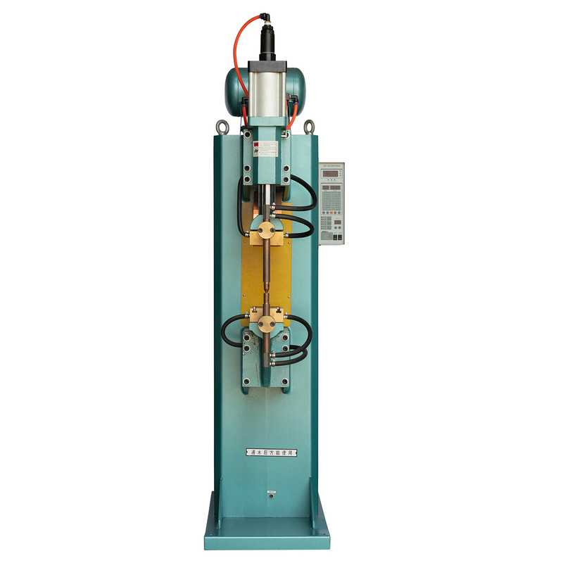
Termen FN-stumsvetsmaskin hänvisar till en familj av motståndsstumsvetsutrustning byggd kring samma kärnprincip: klämma fast två ändar, applicera ström och tryck och smält gränssnittet. Skillnaden mellan modellerna ligger i hur klämkraften och strömmen styrs, vilket i sin tur avgör materialutbudet, fogkvaliteten och produktionshastigheten varje variant är lämpad för.

Tre konfigurationer täcker de flesta behov av tråd- och stångskarvning som finns i tråddragningslinjer, fjädertillverkning, nättillverkning och tillverkning av bandsågblad:
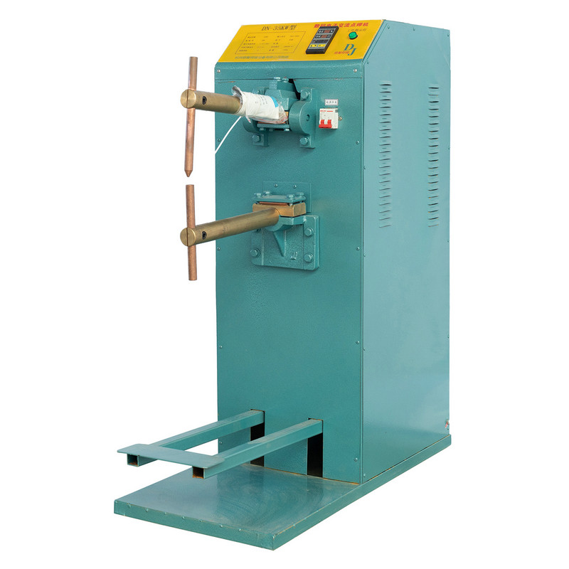
Den UN1 Handmanövrerad stumsvetsmaskin förlitar sig på en spakpåverkad klämmekanism som manövreras direkt av teknikern. Eftersom operatören kontrollerar både stängningshastigheten och uppehållstrycket genom känsla, fungerar denna konfiguration bra i inställningar där tråddiametrar eller stångsektioner ändras ofta och en fast automatiserad cykel skulle behöva konstant omprogrammering.
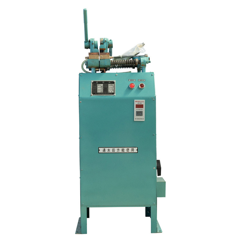
Verkstäder som reparerar trasig dragtråd i mitten av körningen, verktygsrum som förbereder testkuponger eller stationer för vävning av små nät tenderar att gynna denna konfiguration eftersom inställningstiden är minimal och ingen tryckluftstillförsel krävs. Avvägningen är att fogkonsistensen delvis beror på operatörsteknik, så träning och en dokumenterad klämprocedur är viktigare här än med automatiserade varianter.
| Attribut | Typiskt beteende |
|---|---|
| Aktivering | Manuell spakklämma |
| Bäst lämpad diameterområde | Tunn till medium tråd och liten stav |
| Lufttillförsel behövs | Nej |
| Cykelkonsistens | Operatörsberoende |
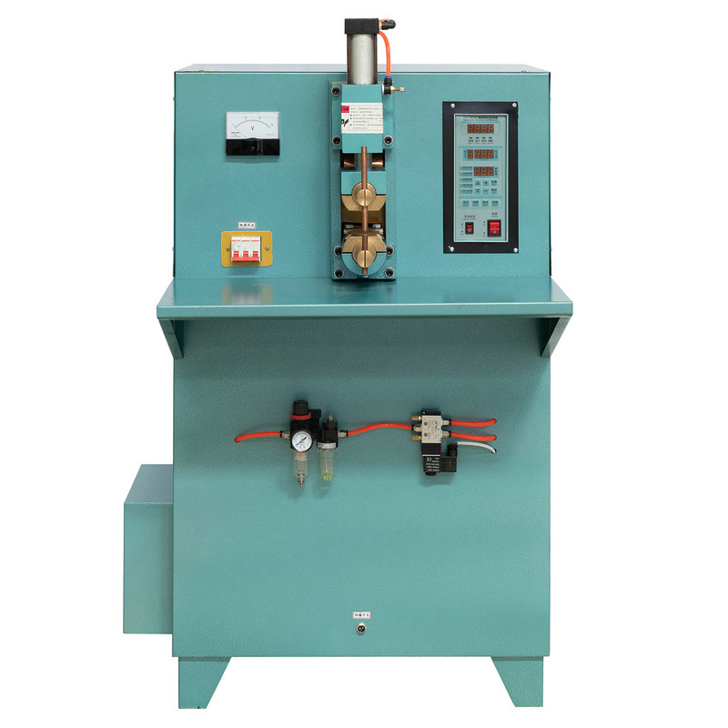
Den UN2 Pneumatic Butt Welding Machine replaces the manual lever with an air cylinder, so the clamping force stays consistent from the first weld of the shift to the last. This matters in continuous production because joint quality drifts noticeably once operator fatigue affects manual clamping pressure over hours of repetitive cycles.
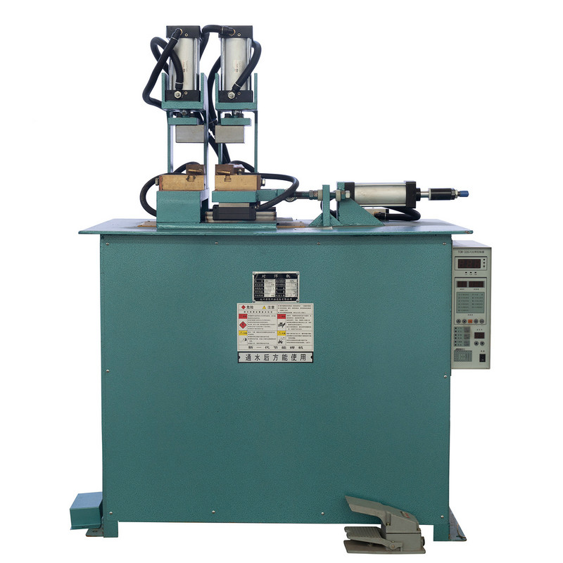
Linjer som matar tråddragningsmaskiner, kallkursutrustning eller kontinuerliga galvaniseringsbad integrerar vanligtvis denna typ av svetsare direkt före processen, eftersom en missad eller svag fog nedströms kan skada verktyget mycket dyrare än svetsaren själv.
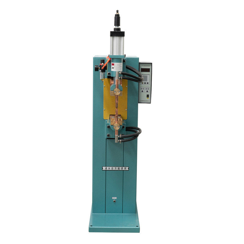
Den UN3 Flash-stumsvetsmaskin använder en annan fysisk mekanism än motståndssvetsning. Istället för att applicera fullt tryck innan ström flyter, bringar maskinen de två ändarna i intermittent kontakt medan ström redan är pålagd, vilket ger en snabb serie av små bågar, eller blinkningar, som rengör och värmer gränsytan innan en slutlig smideskraft smälter samman fogen.
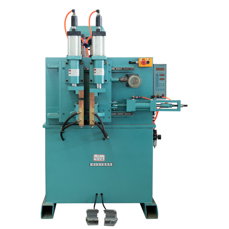
Den flashing action burns off surface oxides and contamination from the mating faces before the forging stroke occurs, which is difficult to achieve with straight upset welding once the cross section grows beyond thin wire. This is why flash butt welding is the preferred process for larger rod diameters, band saw blade backs, and rolled ring stock where a clean, low-inclusion joint is critical to fatigue life.
Fältobservation: Tillverkare av sågblad rapporterar konsekvent att snabbsvetsade fogar håller bättre vid upprepad böjning runt hjulstyrningarna än fogar gjorda med okomplicerad motståndssvetsning på samma materialtjocklek, till stor del på grund av att flashningssteget tar bort ytoxidskikt som annars skulle sitta inuti svetsgränsytan.
Att förstå sekvensen hjälper till att förklara varför fogkvaliteten är så repeterbar när parametrarna väl har ställts in. Processen går genom fyra distinkta faser, som var och en kontrollerar olika aspekter av den slutliga fogen.
Varje fas är tidsinställd snarare än att bedömas efter känsla, vilket är just därför som maskinstyrd snabbstumsvetsning ger mer konsekventa fogar än en rent manuell process när diametern eller legeringen ändras.
Att välja lämplig tråd för svetsmaskinens drift handlar lika mycket om maskininställningen som själva materialet. Samma tråddiameter kan bete sig olika beroende på ytbeläggning, härdning och legeringssammansättning, som alla förändrar strömmen och trycket som behövs för en ren fog. Operatörer som köper tråd för svetsarmatningslinjer bör behandla dessa variabler som en del av svetsreceptet, inte bara en inköpsspecifikation.
| Materialskick | Sammanfogningsövervägande |
|---|---|
| Ljusdragen ståltråd | Enkel motståndssvetsning, minimal rengöring behövs |
| Galvaniserad tråd | Beläggningen måste avskalas nära fogen för att undvika porositet |
| Rostfri tråd | Högre resistans kräver noggrann strömjustering |
| Härdad fjädertråd | Fogzon behöver ofta eftersvetsglödgning för att återställa duktiliteten |
Som en generell princip gynnar tunnare tråd svetsning av motståndsstörningar på handmanövrerade eller pneumatiska maskiner, medan tjockare stång och bandmaterial drar fördel av den rengöringsverkan som snabbsvetsning ger. Att matcha maskintypen till materialprofilen minskar efterarbete och håller fogbrottsfrekvensen låg över långa produktionsserier.
Den practical value of these machines becomes clearer when mapped against the operations that depend on continuous strand supply:
I varje fall är det underliggande målet identiskt: eliminera stilleståndstiden och skrot som kommer från omlastning av råmaterial, samtidigt som fogen hålls tillräckligt stark för att nedströmsverktyg aldrig registrerar det som en defekt.
Slitage av elektroder och klämmor är den vanligaste orsaken till gradvis försämring av fogkvaliteten på all stumsvetsutrustning. När klämbackarna slits, ökar kontaktmotståndet ojämnt, vilket visar sig som inkonsekvent störningsbildning även när den aktuella inställningen inte har ändrats. En kort daglig inspektionsrutin fångar upp detta innan det påverkar en fullständig produktionskörning.
En fog som ser rent visuellt ut men som inte klarar ett böjtest spårar nästan alltid tillbaka till antingen förorenade sammankopplingsytor eller en klämkraft som har glidit utanför räckvidden, inte en grundläggande processbegränsning.
Motståndssvetsning applicerar fullt spänntryck innan ström flyter och förlitar sig på värme plus tryck för att smälta ihop rena, förberedda ändar. Snabbstumsvetsning introducerar intermittent ljusbåge före smidesslaget, vilket rengör de passande ytorna som en del av cykeln, vilket gör den bättre lämpad för större sektioner eller mindre orörda material.
De flesta stumsvetsmaskiner är klassade för ett specifikt diameterintervall eftersom klämkraft, strömkapacitet och elektrodgeometri är anpassade till det området. Löpande material utanför det nominella intervallet ger vanligtvis inkonsekventa fogar även om maskinen fysiskt accepterar materialet.
När parametrarna är korrekt anpassade till materialet och fogen är korrekt trimmad och vid behov avlastad, kan fogen närma sig den omgivande trådens draghållfasthet. Faktiska resultat varierar beroende på legering, diameter och eftersvetsbehandling, så provprovning på varje ny materialsats rekommenderas.
Inte nödvändigtvis. Pneumatiska enheter erbjuder konsistens och hastighet för körningar med stora volymer, men handmanövrerade enheter förblir praktiska för arbete med små volymer, frekventa diameterbyten eller platser utan tillförlitlig tryckluftstillförsel.
Ja. Beläggningar som zink kan förångas under svetsning och lämna porositet eller inneslutningar i fogen om de inte rengörs tillbaka från svetszonen i förväg. Att strippa eller maskera beläggningen nära fogområdet förbättrar vanligtvis svetsintegriteten.
Rekommenderade produkter

Produkt
Kontaktinformation.
+86-152-5712-5882
Fax: +86-563-2269966
Nr 21 Guangping Road, Guangde Economic Development Zone, Guangde City, Anhui -provinsen
QR -kod